Operating Principle of Planetary Gearboxes and Gear Ratio Calculations Based on Application Scenarios
Operating Principle of Planetary Gearboxes and Gear Ratio Calculations Based on Application Scenarios
1. Introduction
Planetary gear systems are widely used in industry due to their compact structure, high torque transmission capabilities, and low backlash. They are commonly preferred in robotics, automotive, defense industry, aerospace, wind turbines, and construction machinery applications.
2. Main Components
A planetary gearbox typically consists of the following main components:
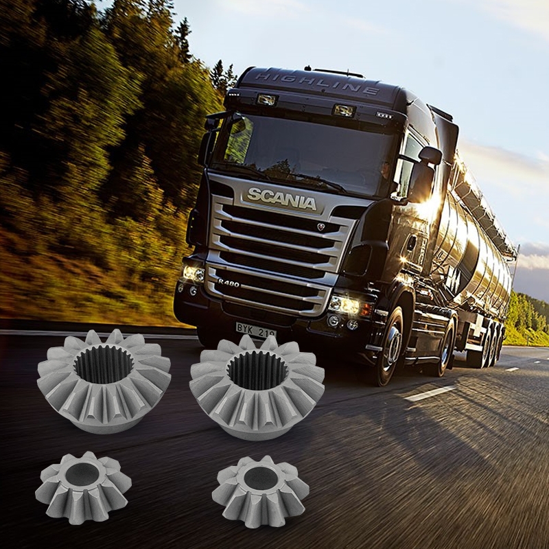
• Sun Gear: Located at the center of the system and often serves as the input.
• Planet Gears: Rotate around the sun gear and simultaneously engage with both the sun gear and the ring gear.
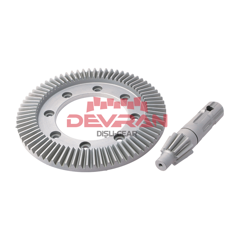
• Ring Gear: A ring-shaped gear with internal teeth that meshes with the planet gears.
• Carrier: Holds the planet gears and usually acts as the output element.
3. Working Principle
Planet gears revolve around the sun gear while rotating on their own axes. During this motion, they stay in constant mesh with both the sun and ring gears. Torque is transmitted through these gears, and the system's output depends on which component is fixed, which is the input, and which is the output.
Advantages of planetary gear systems include:
• High torque in compact volume
• High efficiency
• Symmetrical load distribution
• Compact structure
4. Gear Ratio (Transmission Ratio)
The transmission ratio is defined as the ratio between the input and output speeds. In planetary gear systems, the ratio varies depending on the gear configuration and which component is held stationary.
Most common formula (when the ring gear is fixed, sun is input, and carrier is output):
i = 1 + (Zr / Zs)
Where:
• Zr: Number of teeth on the ring gear
• Zs: Number of teeth on the sun gear
• i: Transmission ratio
5. Scenarios Based on Input and Output Elements
Scenario 1: Sun Gear Input, Ring Gear Fixed, Carrier Output
Usage: Most common for speed reduction
Transmission Ratio:
i = 1 + (Zr / Zs)
Result: Output is slower and delivers higher torque. Rotation direction remains the same.
Scenario 2: Carrier Input, Ring Gear Fixed, Sun Gear Output
Usage: Suitable for speed-increasing applications
Transmission Ratio:
i = 1 / (1 + (Zr / Zs))
Result: Output speed increases. Rotation direction remains the same. Torque decreases.
Scenario 3: Sun Gear Input, Carrier Fixed, Ring Gear Output
Usage: When reverse output direction is required
Transmission Ratio:
i = - (Zr / Zs)
Result: Output rotates in the opposite direction. High reduction is achieved.
Scenario 4: Ring Gear Input, Sun Gear Fixed, Carrier Output
Usage: When reverse torque or direction is needed
Transmission Ratio:
i = 1 - (Zr / Zs)
Result: Output direction is reversed. Torque direction can be inverted.
6. Conclusion
Planetary gear systems offer a flexible working principle capable of performing various functions with the same mechanical structure. Depending on which component is input, output, or stationary, both the direction of rotation and the speed-torque balance change significantly. This makes them highly valuable and optimizable from an engineering standpoint.
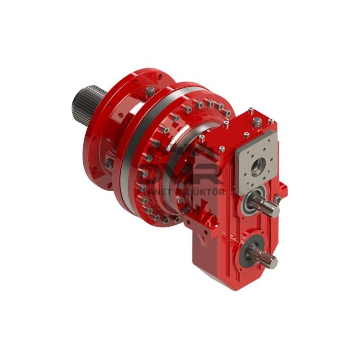
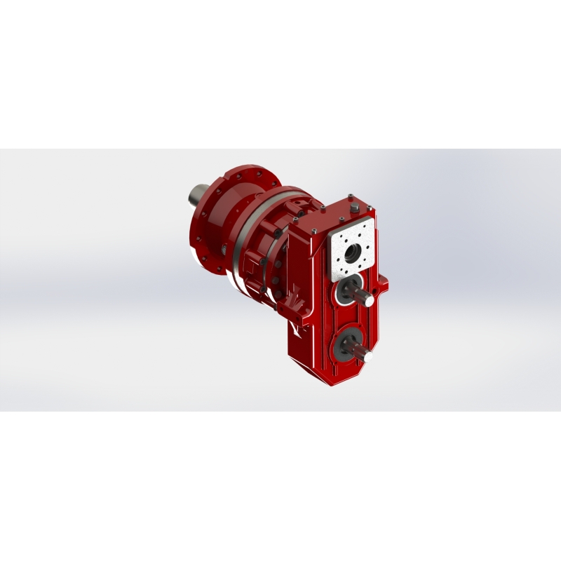
7. Modular System Advantage: Devran Gear – DVR and DVA Planetary Gearbox Series
The DVR and DVA series planetary gearboxes produced by Devran Gear offer a modular system configurable from 1 to 4 stages. These systems provide a wide gear ratio range from 3.5:1 to 3200:1 and can be customized according to different application requirements.
Thanks to the modular design, they offer:
• Various input and output configurations (flange, shaft, coupling, motor adapter, etc.)
• Braking options such as negative spring-applied disc brakes
• Optimal fit for compact spaces or high-torque applications
This flexibility makes the DVR and DVA series planetary gearboxes efficient and reliable solutions in a wide range of industries including construction machinery, mobile hydraulics, cranes, agricultural equipment, mining, and energy sectors.